TL;DR: A control room video wall displays the camera feeds and dashboards that operators act on. A failure takes that information off the wall, and the interruption costs more than in most indoor spaces. Three design decisions set how quickly the wall recovers: power and signal redundancy, the signal path from source to module, and the recovery plan operators rehearse. This guide walks through those decisions, provides an acceptance checklist to complete before sign-off, and lists the inputs a supplier needs to prepare a quote.
Introduction
A video wall planned for a network operations center, a security control room, or a utility dispatch center serves a different purpose from a retail or stage screen. In a retail lobby, a failed module is a cosmetic problem. In a traffic monitoring room, the same failure means part of the road is no longer on screen, and no one is watching that part of the road. That difference decides what to look for when buying: not only size and pixel pitch, but how the wall handles failure. The sections below cover the design decisions that limit the impact of a failure, the acceptance checks that confirm the wall works as designed, and the information to gather before requesting a quote. For an overview of products and application scenarios, the control room and command center solution page covers the replacement decision and where each product line fits. The redundancy guidance here is generic on purpose: specific products support specific configurations, and the supplier confirms those in writing.
Design Requirements for Continuous Operation
A control room display runs continuously. Three consequences follow:
- Heat accumulates. A display under continuous load produces heat the whole time it is powered, so the thermal design of cabinets and power supplies matters more than the peak brightness figure on a datasheet.
- Access matters. Modules and power supplies need to be serviceable from the front in most control rooms, because the display usually backs onto a solid wall with no service corridor behind it.
- Brightness requirements stay moderate. Indoor control rooms use controlled lighting, so the display does not need the brightness levels that daylight-facing installations require. A brightness setting above what the room needs adds power draw and heat without adding readable information, so specify brightness against the room’s lighting conditions rather than against the datasheet maximum. For the outdoor counterpart of this trade-off, see LED brightness and power consumption for European outdoor displays.
The practical conclusion: when comparing products for a control room, weight continuous-duty design and front serviceability above headline specifications.
Redundancy: Design Options and Their Trade-offs
Redundancy means the wall keeps working when one part fails. The options differ in what they protect and what they cost.
Power redundancy comes in two common forms:
- N+1 puts one spare power unit on standby for the whole wall or for each cabinet group. If one unit fails, the spare takes over. This covers a single-unit failure at a moderate cost.
- 1+1 pairs each power unit with its own backup. Any single power-unit failure is covered without any shared capacity, at roughly twice the power-supply cost.
Hot-swappable units add a second dimension: a failed unit can be replaced without powering down the wall. Without hot swap, even a protected system needs a maintenance window for the repair.
Signal and control redundancy protects the path that feeds the image:
- A backup sending unit or controller in hot standby takes over if the primary unit fails.
- Loop (ring) backup at the receiving-card level lets data flow around a broken connection instead of stopping at it.
Each option narrows the set of failures that interrupt the wall, and each adds cost. The selection depends on what the room monitors: a security wall where blanking is unacceptable justifies more redundancy than a display that duplicates a dashboard elsewhere.
One step belongs in every case: ask the supplier to state in writing which redundancy configurations the product supports, and what the wall shows during a switchover. Treat any claim of uninterrupted operation as a question to confirm, not a fact to assume.
Planning the Signal Path
The picture reaches the wall through five stages of equipment, and each stage can fail:
- Sources — workstation outputs, cameras, and video management systems supply the signals to display.
- Video processor — arranges those signals into windows and layouts.
- Sending units — transmit the signal to the wall over copper or fiber.
- Receiving cards — one or more per cabinet, pass the signal on to the modules.
- Modules — produce the image.
Four planning decisions limit the impact of a failure at any stage:
- Match the link type to the distance. Copper cabling covers short runs; fiber covers longer distances and adds immunity to electrical interference. A control room with racks far from the wall usually justifies fiber.
- Choose a topology with a fallback. A star topology connects every cabinet to the sender directly, so one broken cable isolates one cabinet. A loop topology connects cabinets in a ring, so data flows around a break. The right choice depends on the redundancy the receiving cards support.
- Reserve a spare path. A spare sending port and a spare fiber or cable run cost little at installation time and are costly to add later, once cable trays are closed.
- Label and document everything. Give each cable run an ID label at both ends, and keep a list of what each run connects: which sending-unit port feeds which cabinet. When a cabinet freezes or blanks, the list takes operators from that cabinet to the cable and port behind it, so they check one connection instead of pulling and testing cables one by one.
Failure Recovery: What Operations Should Rehearse
Failures come in four classes, and each class has a different recovery action:
| Failure class | What the wall shows | Recovery action |
| Single module fails | Dark or patched area within one cabinet | Swap the module from on-site spares |
| Cabinet power unit fails | One cabinet dims or goes dark | Confirm the spare unit takes over; replace the failed unit |
| Signal link breaks | One cabinet or group freezes or blanks | Switch to the backup path or spare port |
| Controller fails | Whole wall freezes or blanks | Switch to the standby controller; reload the configuration |
Three habits make these actions fast when they matter:
- Keep spares on site at the right level. Modules and receiving cards are the parts that swap fastest; a spare set in the same building turns a days-long wait into a minutes-long repair.
- Keep configuration backups off the device. After every layout or calibration change, export the configuration file and store it with the project documents. A replacement controller restores the wall in minutes only if its configuration exists somewhere else.
- Rehearse during acceptance, not during the first incident. Pull one power feed, disconnect one link, and restart the controller while the installer is still on site. The rehearsal doubles as an acceptance test.
The Acceptance Checklist Before Sign-off
Acceptance works when the criteria are written down before the test. The table below defines the checks; the numerical thresholds belong in the contract, agreed with the supplier in writing.
| # | Check | Method | How to write the pass criterion |
| 1 | Brightness and color uniformity | Measure a sample of positions across the wall with the same meter and settings | State the maximum permitted variation as a percentage agreed in the contract |
| 2 | Dead pixels and module defects | Inspect the full wall with test patterns (full white, full black, primary colors) | State the accepted count per cabinet and per wall; state “zero dead pixels” only if the contract guarantees it |
| 3 | Flatness and seams | Check cabinet joints with a straightedge and inspect the grid from the first-row viewing distance | State the maximum permitted step at cabinet joints and “no visible grid at [distance]” |
| 4 | Grayscale and low-signal image | Display dark test patterns; check that shadow detail does not band or posterize | Describe the accepted image quality on the agreed test patterns |
| 5 | Redundancy paths | Pull one power feed; disconnect one signal link; restart the controller | State the required wall behavior for each test, as confirmed by the supplier in writing |
| 6 | Documentation handover | Collect calibration archive, configuration backup files, manuals, and spares list | List each document by name; acceptance is incomplete without them |
Item 5 tests the redundancy design under real failure conditions. Run each test during acceptance, and compare the wall’s behavior with the switchover behavior the supplier described in writing.
Sightlines, Viewing Distance, and Pixel Pitch
The first row of operator desks sets the pixel pitch. Operators who sit close to the wall need small pitch to avoid seeing the pixel grid; the practical rule of thumb divides the viewing distance in meters by 1.2 to estimate the pitch in millimeters. A control room with a first row at 2 meters points to a pitch around 1.7 millimeters; closer rooms call for finer pitch.
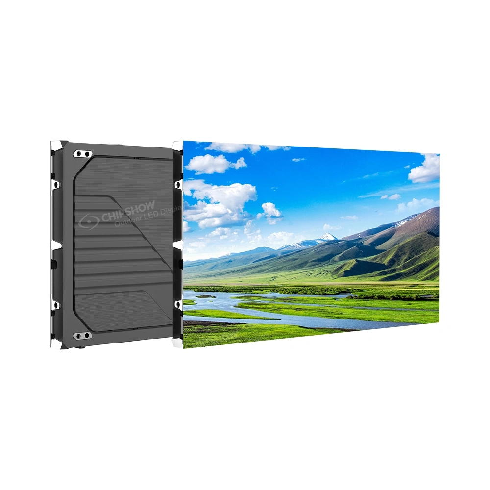
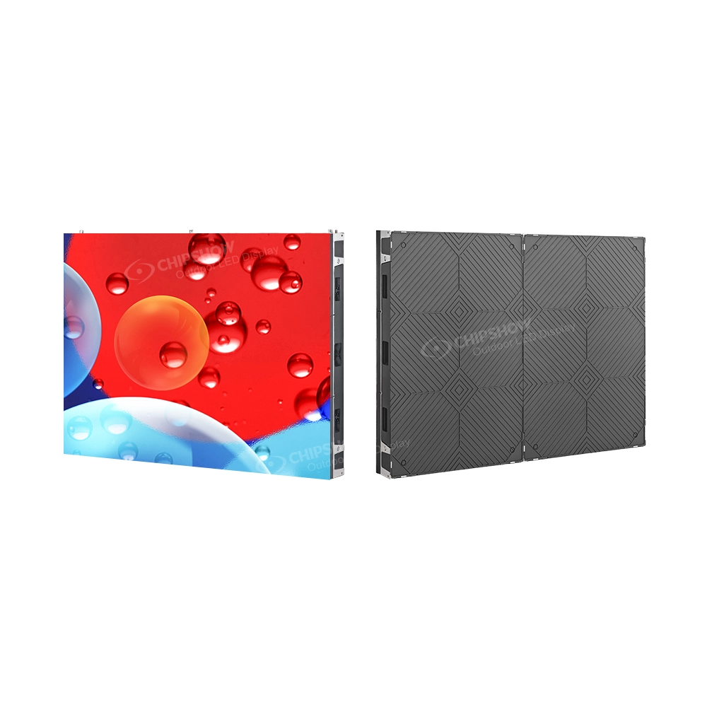
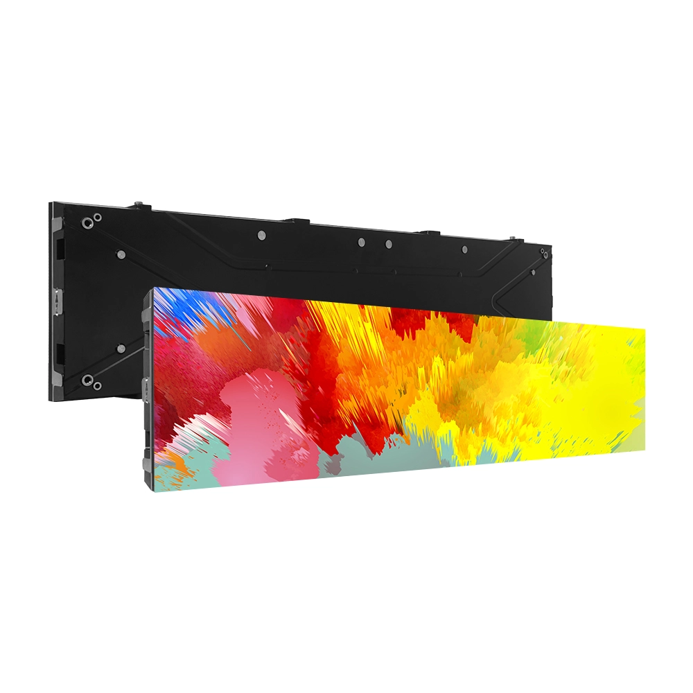
Two current product lines serve this close-viewing range: the C-Pad-C fine-pitch COB series covers P0.78 to P1.87 for close-viewing rooms, and the C-Max COB series covers P1.25 to P1.86 in a 4:3 cabinet format that maps onto legacy surveillance wall grids.
Sightlines also decide the wall’s height and center. The wall should sit so that every operator sees the information zones they own without leaning or standing, and so that no cabinet line crosses the most-read area at eye level. Mark the sightlines on the room drawing before the layout is finalized, not after the cabinets arrive.
What to Prepare Before Requesting a Quote
A supplier can quote precisely when the request contains these inputs:
- First-row viewing distance and the room’s dimensions, which set the pitch and the wall size
- Target resolution, derived from what the wall must show at once: how many camera feeds, dashboards, or map windows in the busiest layout
- Signal source list: workstation outputs, video management system, and their connector types
- Service access conditions: whether the wall can be serviced from the front only, and what space exists behind it
- Room environment: operating temperature range, humidity, and dust exposure
- Operating schedule: continuous 24/7 duty versus extended-hours operation, which sets the redundancy level
Chipshow supplies fine-pitch indoor LED video walls for control room and dispatch center applications, with project delivery experience in data center and security dispatch environments. Send the inputs above through the contact page to receive a configuration quoted against real room conditions rather than assumptions.
FAQ
Q1:COB or SMD modules for a control room video wall?
Choose by room, not by technology label. Chipshow’s COB lines, the C-Pad-C and C-Max COB series, carry front IP54 protection on the module face and cover the close-viewing pitches from P0.78 to P1.87; the C-Max Commercial SMD line extends to coarser pitches that suit rooms with longer viewing distances. Compare the protection rating and the pitch steps of each model against the room’s first-row distance and its cleaning conditions.
Q2:Do operators seated at the side of the room see the wall correctly?
Compare the viewing angle in the product datasheet with the widest off-axis seat on the room plan. Chipshow’s COB lines, the C-Pad-C and C-Max COB series, are rated at 160 degrees horizontal and vertical, and the C-Max Commercial SMD line at 120 degrees; beyond the rated angle, contrast and color drop off. Measure the largest off-axis angle in the room before the desk layout is finalized.
Q3:Can operators hear the video wall running?
That depends on the cooling design, and a quiet control room makes it worth settling before the order. Fanless cabinets, such as the C-Pad-C and C-Max COB lines, produce no fan noise; cabinets that use fans are audible at close distances. Ask the supplier for an acoustic figure for the specific model.
Q4:What is the calibration archive that acceptance hands over?
It is the stored uniformity correction data for the whole wall: the per-module correction values measured when the wall is commissioned. Ask for it at handover because it is the baseline of the wall’s image quality, and service teams compare against it when a module is replaced later. Confirm with the supplier how the archive is delivered and how it is reapplied after a module swap.