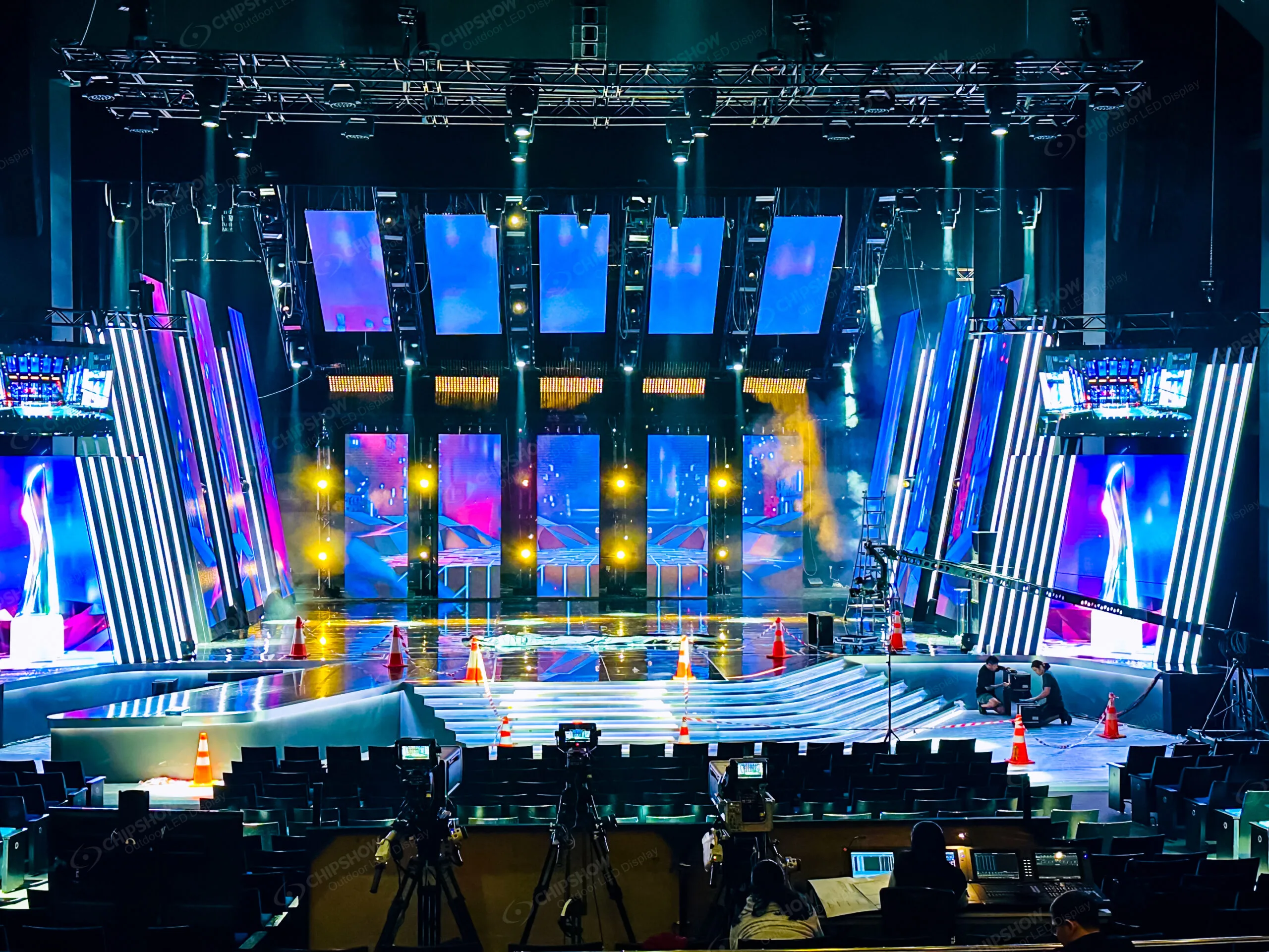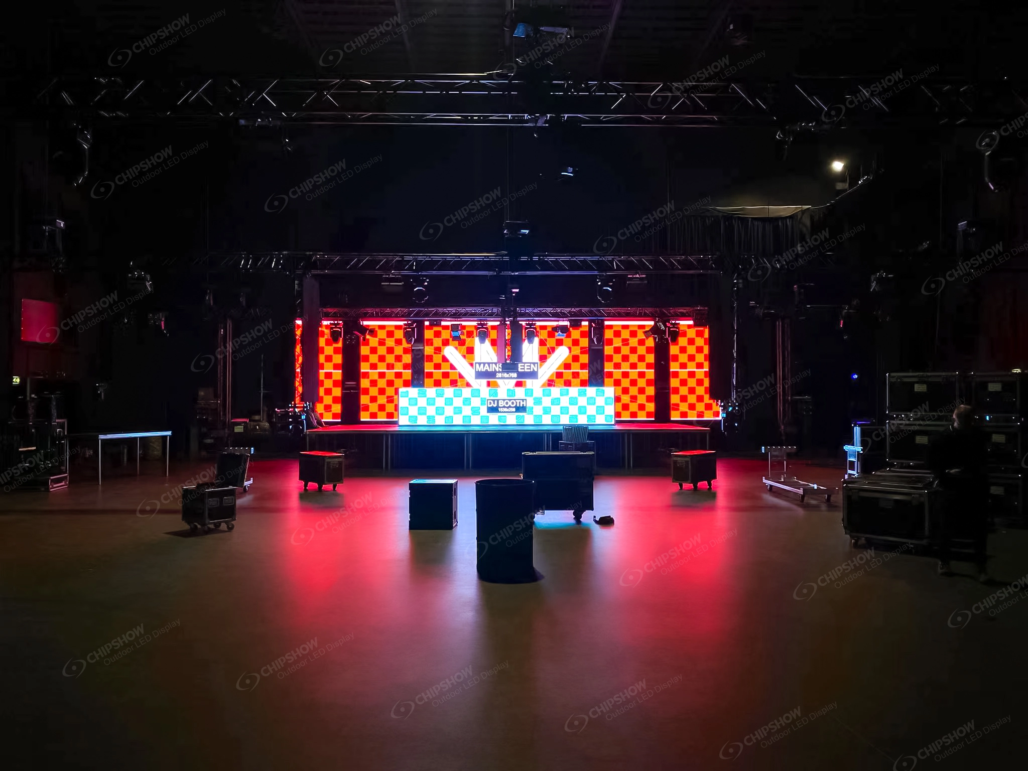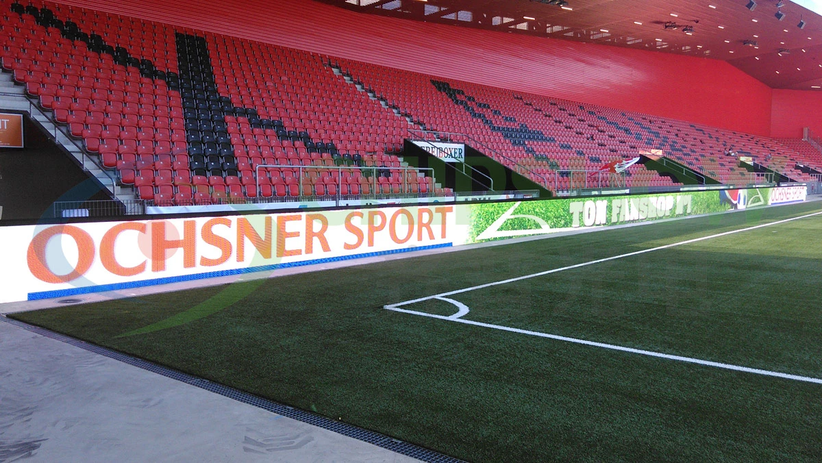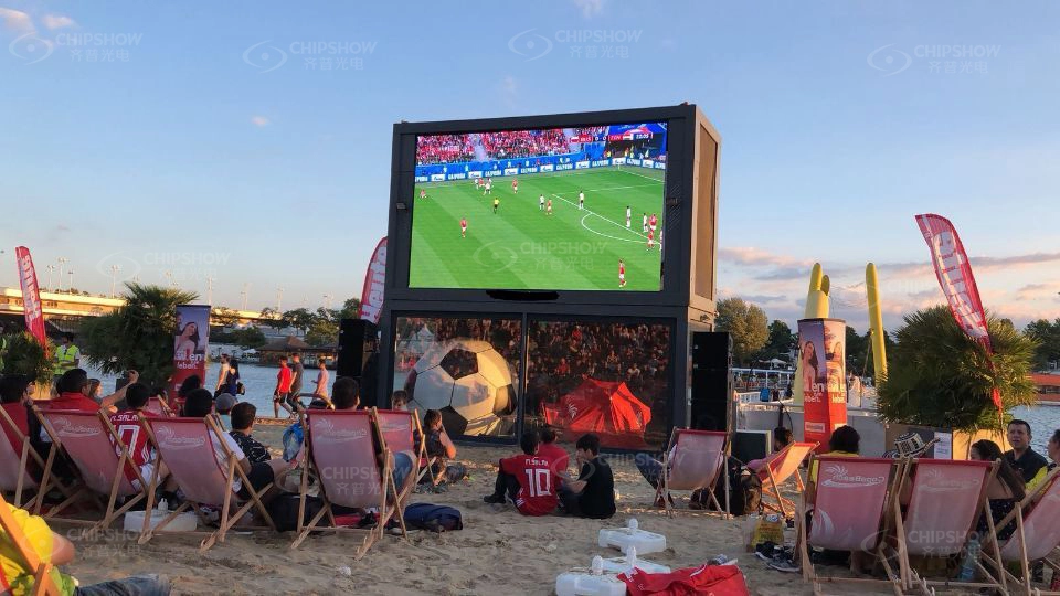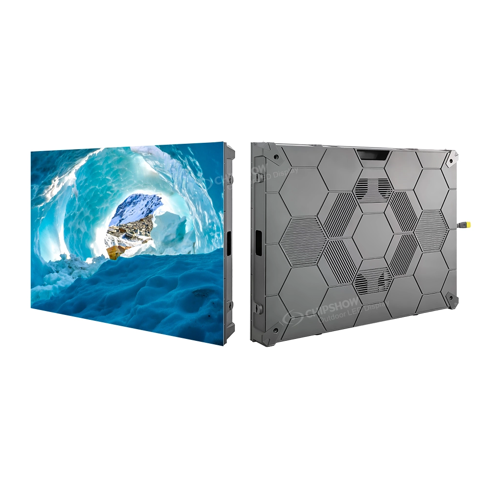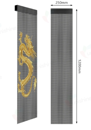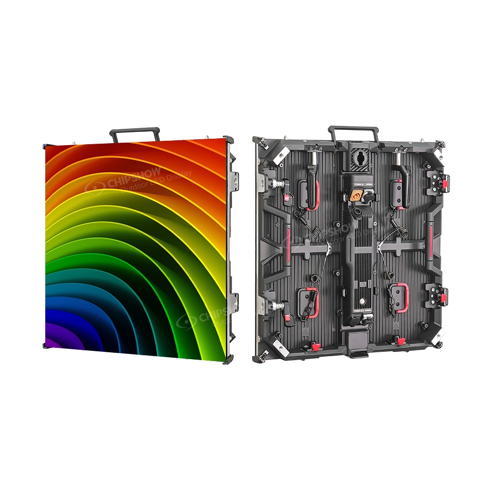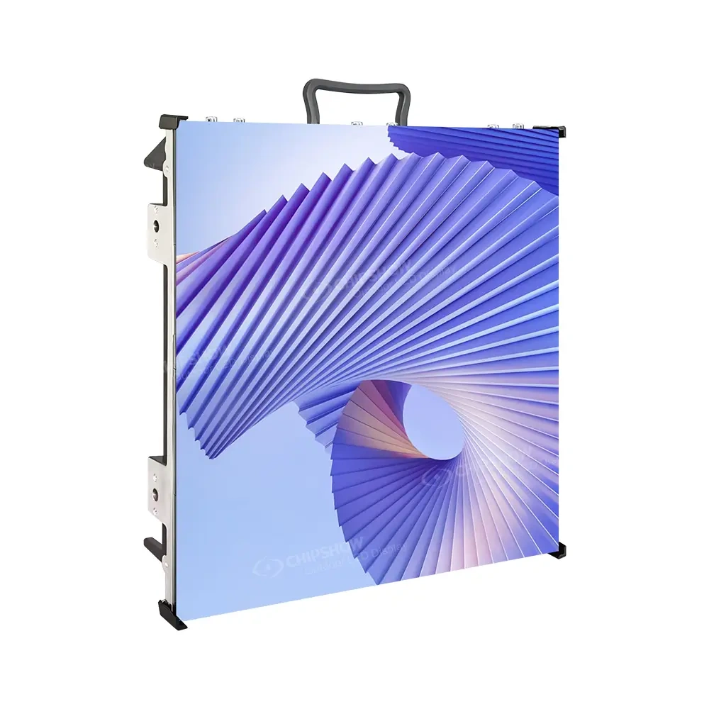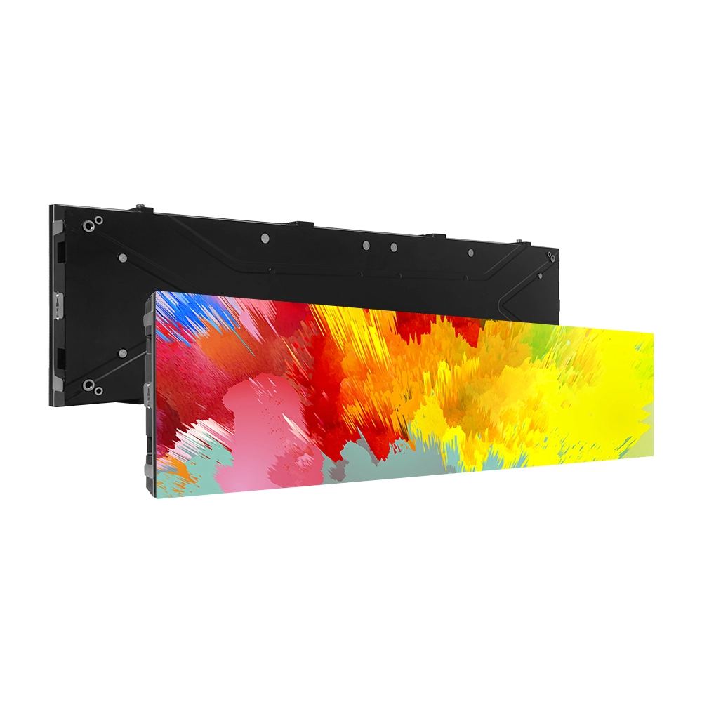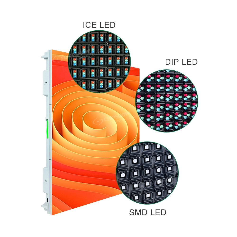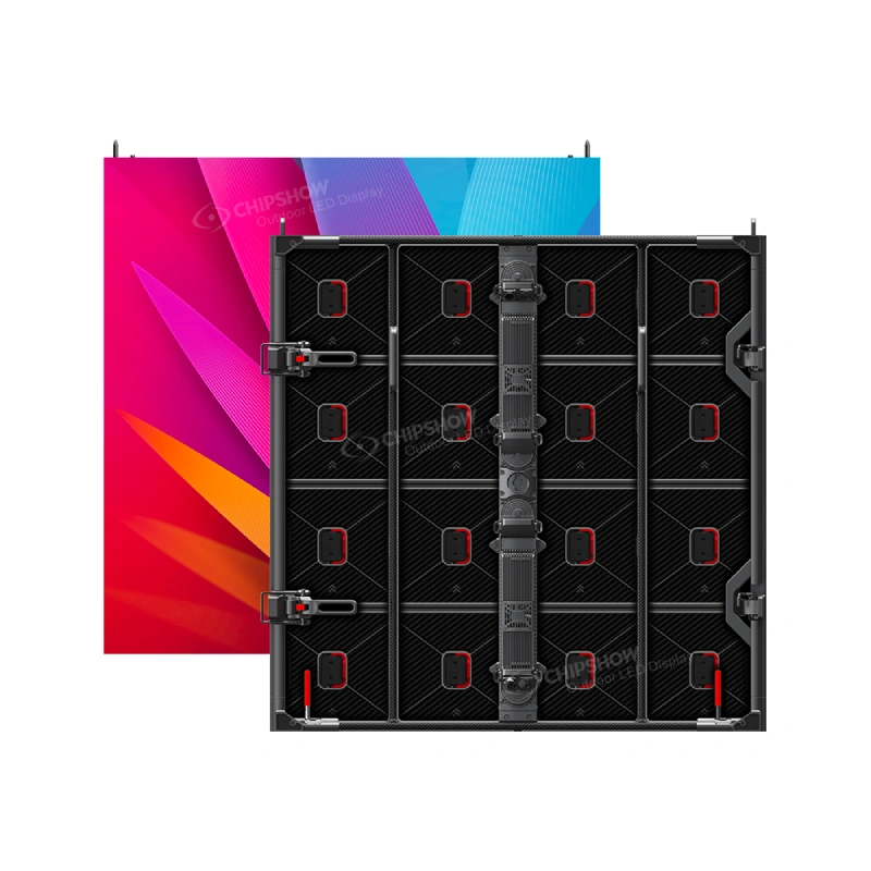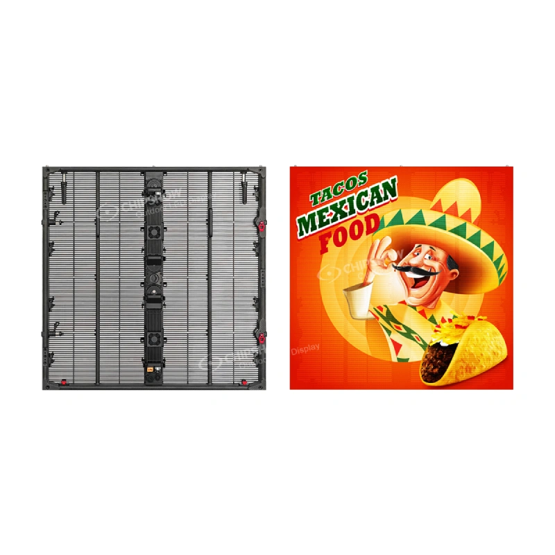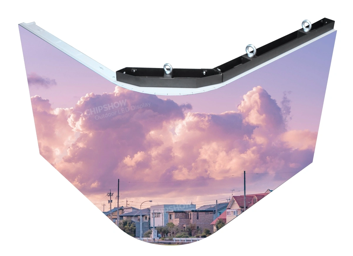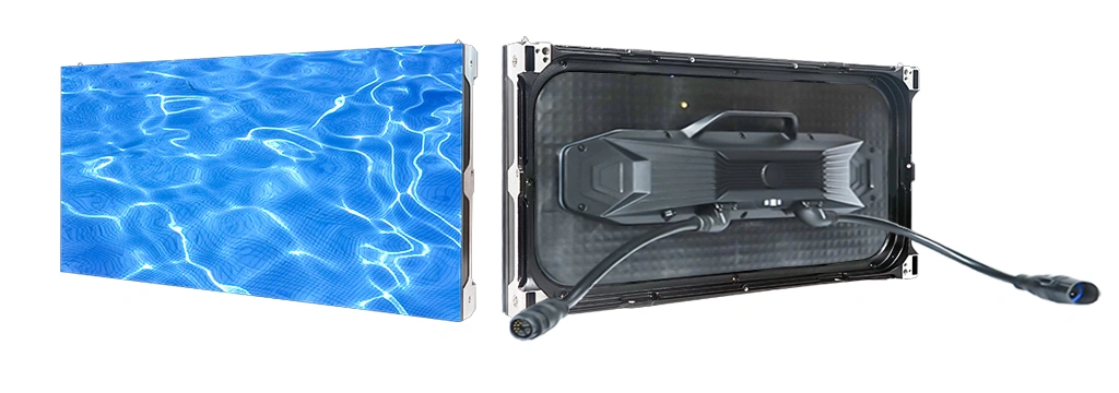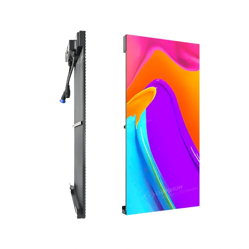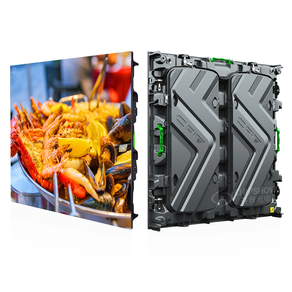
A rental LED cabinet set supports only the screen dimensions its cabinet grid allows. Mixing compatible cabinet sizes can add layout options, but screen proportions still depend on the resulting width and height. Flat, right-angle and curved layouts depend on different cabinet features; compatibility needs confirmation for each combination. For multiple screens running together, assess power demand, processor capacity and output allocation across the full configuration, rather than checking only the largest screen.
Introduction
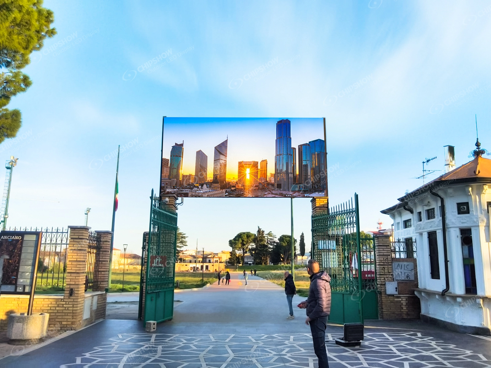
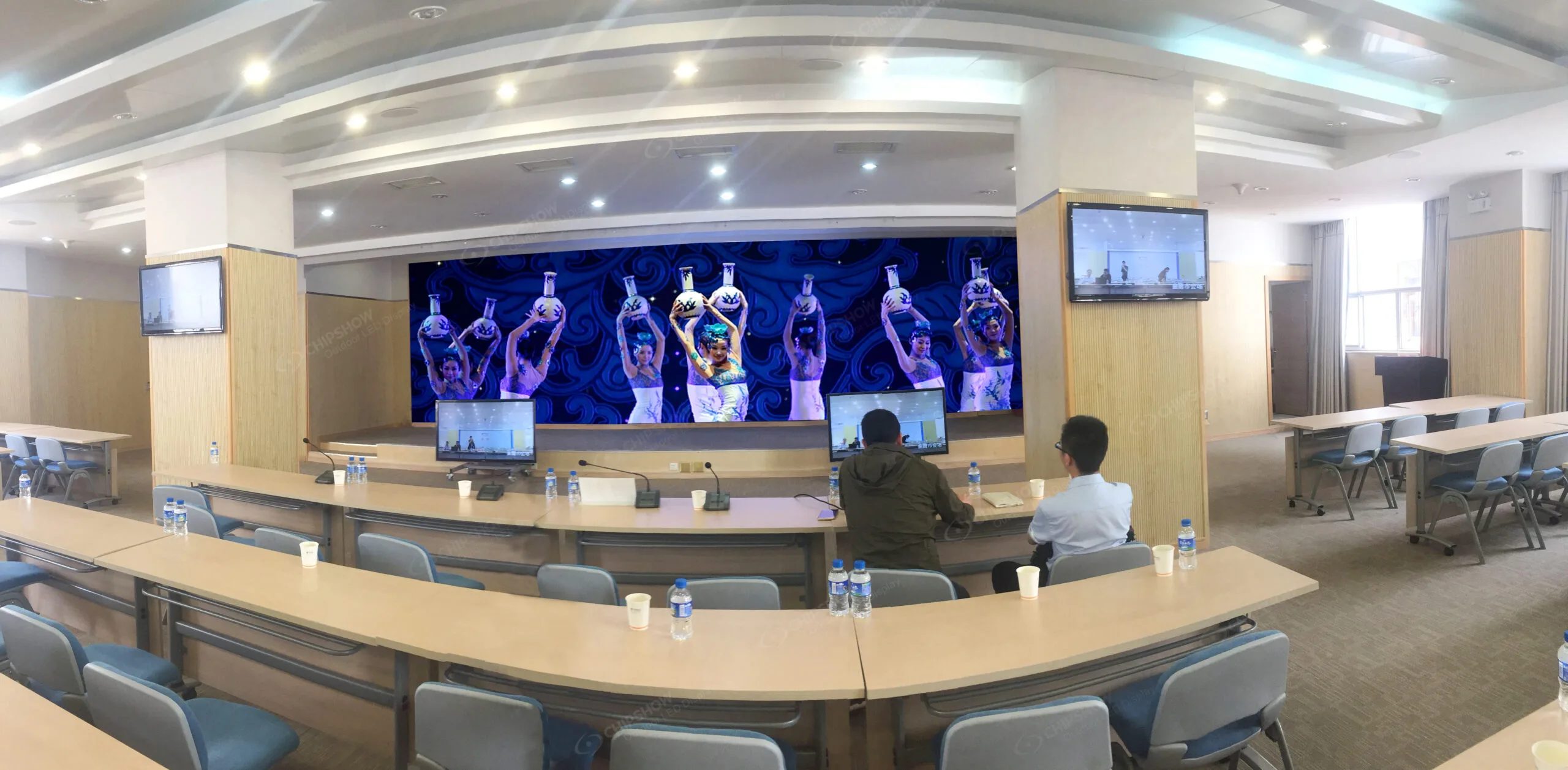
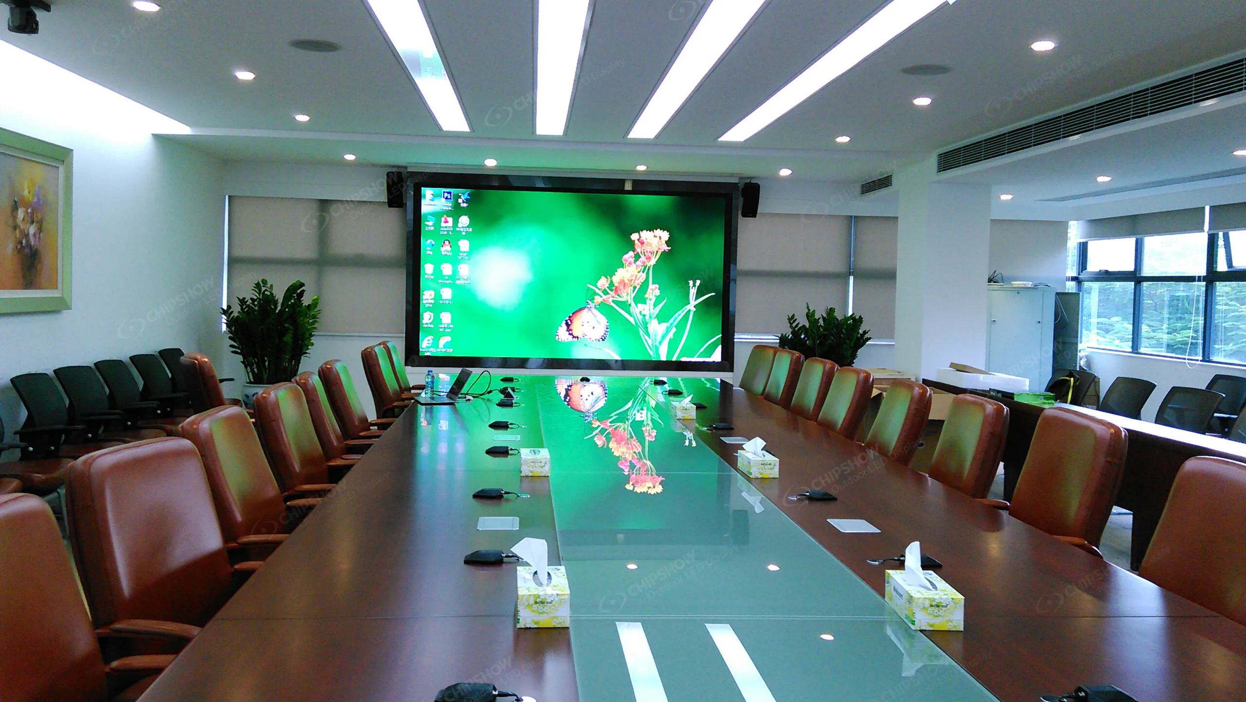
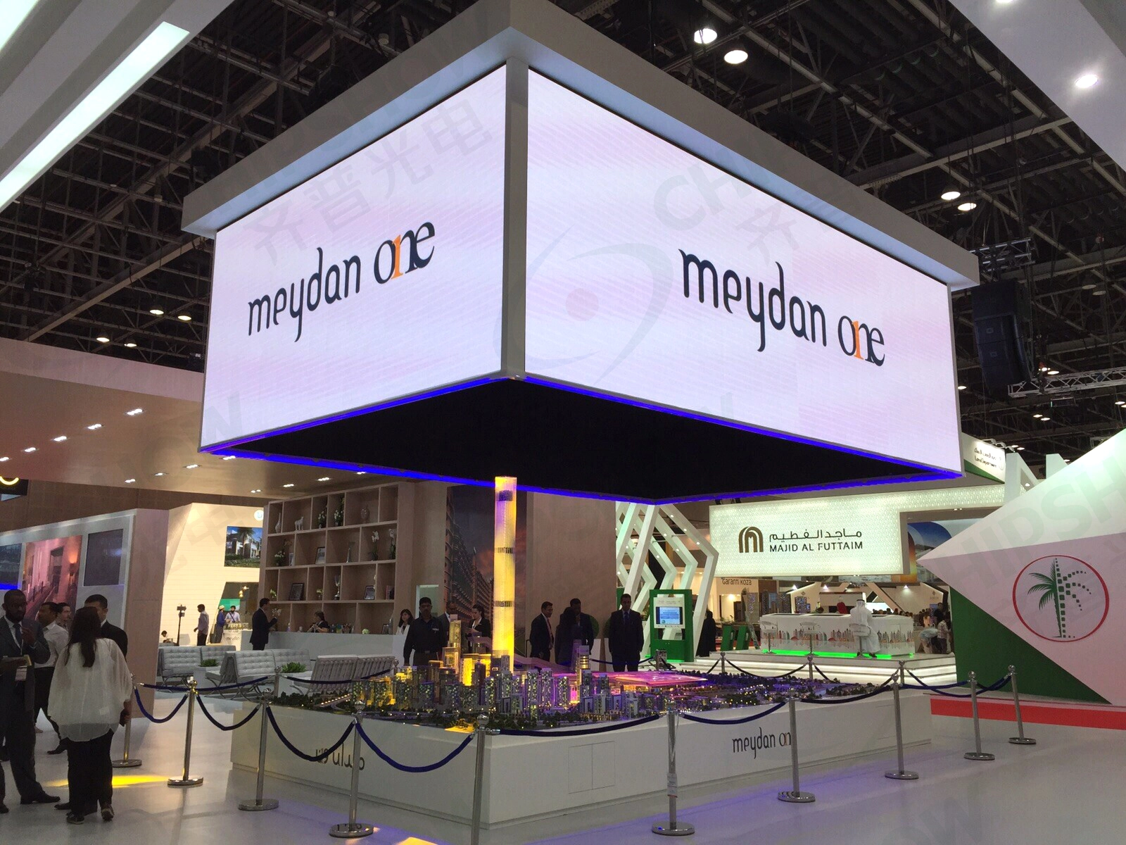
Compare the cabinet set against the screen layouts planned for upcoming events. These may include a conference backdrop for 16:9 content, a tall exhibition wall, or a touring screen with a curved section or corner. For each layout, identify whether the selected cabinets can form the required screen or whether another cabinet type is needed.
For each planned layout, record the cabinet arrangement it needs and the supporting equipment behind it. Use the configuration table at the end of this guide to request confirmation from the supplier and project engineer.
For pixel pitch, brightness and weight selection, see the rental LED screen comparison guide. For deployment options, see the event and stage rental LED solution. This article focuses on the screen sizes and layouts the selected cabinets can be arranged into.
Define the Planned Event Configurations
List the screen configurations each event is expected to need. Record five details for each configuration:
- Target screen width and height. The physical size expected at the venue.
- Content frame. The aspect ratio the live feed, presentation or playback file is produced in.
- Shape. A flat wall, a right-angle corner, a curved section, or a cylinder.
- Mounting position and method. Ground-supported, flown from a structure, or fixed to a wall or truss.
- Environment and duration. Indoor or outdoor, and whether the build happens once or repeats across a tour.
Separate layouts needed for regular events from occasional creative requests when defining what the cabinets must support.
Mark any unconfirmed venue dimensions, content requirements or client requests as pending. Record who will confirm each item, and resolve any requirement that affects cabinet selection or quantity before the configuration is fixed.
For events with several screens, list each screen separately and specify what it will display and how it will be controlled. For screens built at the same time, total the cabinets required by size and model, and check that the available cabinets cover the full configuration.
Check Screen Dimensions and Proportions
Start with the cabinet sizes and quantities to list the wall dimensions the set can build. Check the aspect ratio and pixel matrix of those walls, then assess whether mixing compatible cabinet sizes can provide additional dimension options.
Which Sizes the Cabinets Can Build
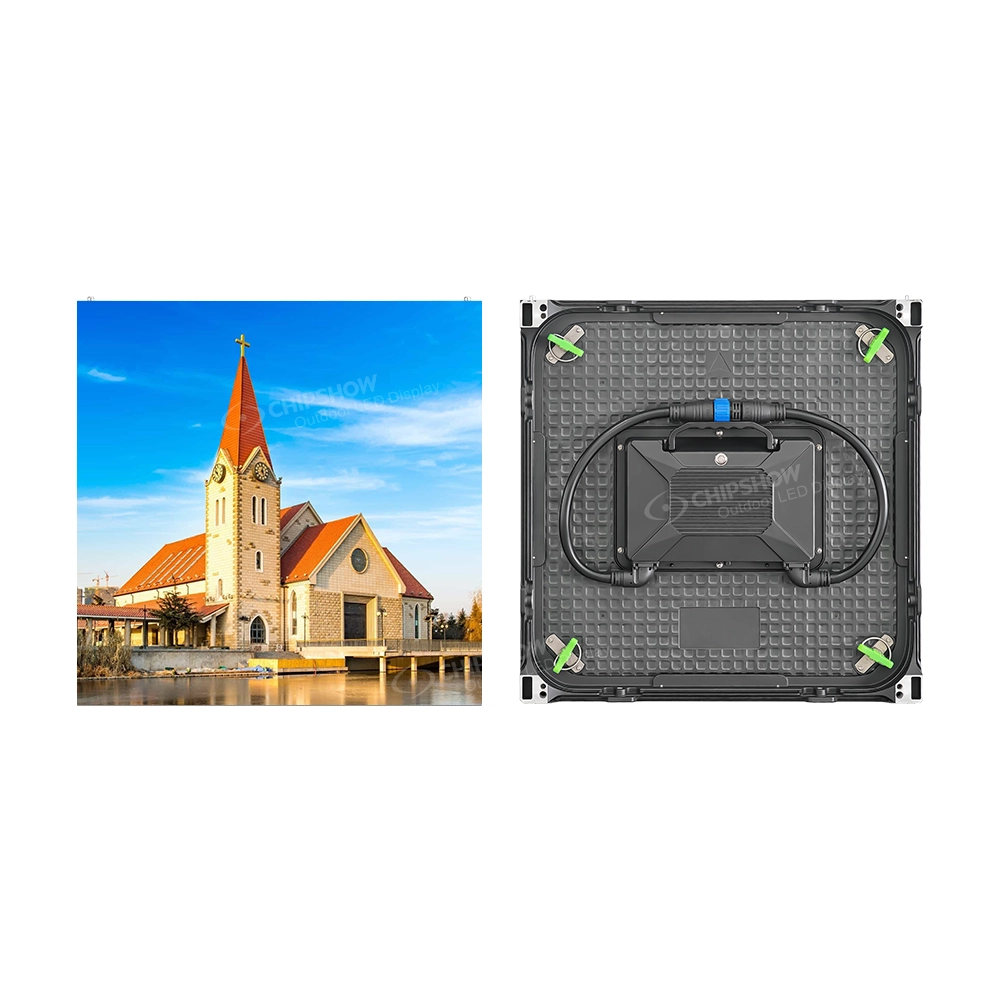
An LED wall is assembled from whole cabinets, so its width and height are sums of cabinet dimensions. The examples below use 500 × 500 mm, one of the cabinet sizes in Chipshow’s rental ranges for small and mid-size events. A wall built from cabinets of this size can be 500 mm, 1,000 mm or 1,500 mm wide or high, and nothing in between.
The same cabinets can be rearranged into different rows and columns to produce different wall sizes. Twelve 500 × 500 mm cabinets can build a 2,000 × 1,500 mm wall in four columns of three, or a 1,500 × 2,000 mm wall in three columns of four. Both use the same twelve cabinets, so a wider arrangement leaves fewer cabinets for the rows and the wall ends up shorter. How large the wall can be depends on how many cabinets there are.
The cabinet sizes and the number of cabinets available therefore decide the widths and heights available. List them, then match the list against the screen dimensions recorded for each planned event. A matching layout passes the size and cabinet-quantity check; its pixel matrix, connections and supporting equipment still need assessment. If a target size falls outside the list, select a wall size the set can build, or consider whether a different cabinet size is needed. Then adapt the content to the selected wall.
Aspect Ratio and Pixel Matrix
Check both the physical width-to-height ratio and the total pixel resolution of each planned wall. If the screen and content aspect ratios differ, decide whether to revise the wall dimensions, reformat the content, crop it, or display it with unused screen areas. The cabinets’ pixel dimensions and their arrangement determine the finished pixel matrix. Then check whether the content stays legible at the intended viewing distance. A wall can match the required physical dimensions and still not have enough pixels for the content.
Mixing Two Cabinet Sizes
When the selected cabinets cannot form a planned height, check whether another compatible cabinet size can complete the required combination. The result depends on the two sizes, their permitted connection direction and the quantities available.
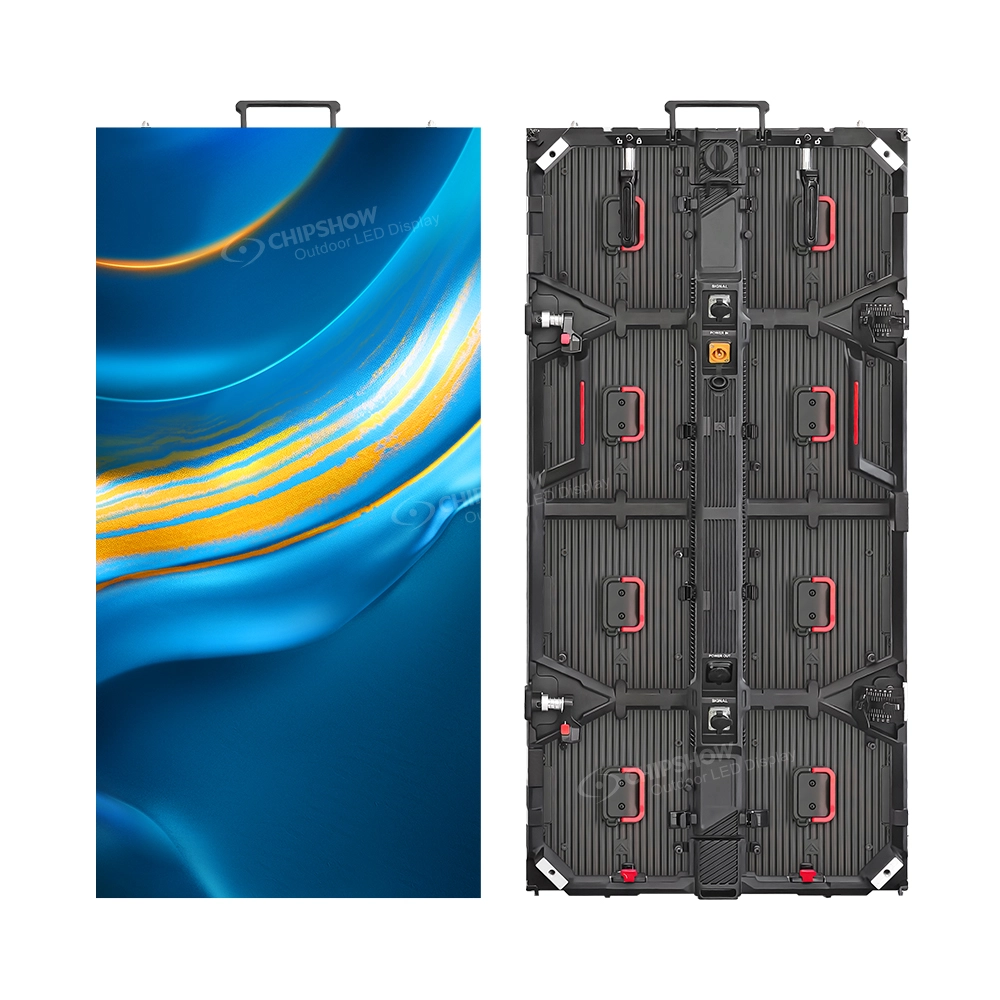
For example, start with the 500 × 1000 mm cabinets in the C-Shine Plus range, used vertically with the 1000 mm side as the height. Adding one compatible 500 × 500 mm cabinet produces a 1500 mm-high column. Both sizes are 500 mm wide, and the range supports stacking them vertically. To repeat this mixed-size arrangement across a rectangular wall, allow one cabinet of each size per column and check the total quantities against the intended width. This is a dimension calculation; the complete arrangement still needs structural confirmation.
Confirm the specific models and permitted connection direction against the supplier’s assembly drawing. The two sizes share locking mechanisms within C-Shine Plus; vertical combinations of 500 × 500 mm and 500 × 1000 mm cabinets are also documented within C-Rock Outdoor. Plan these ranges as separate systems, and ask the supplier to confirm any proposed cross-range combination.
For each mixed-size layout, check the resulting aspect ratio and pixel matrix, then confirm its supporting equipment.
Verify Curves and Corners
| Planned shape | Cabinet feature it depends on | Record per layout |
| Flat wall | Straight connections between cabinets | Achievable width, height and pixel matrix |
| Right-angle corner | Corner edges or a dedicated corner cabinet | The corner arrangement, in the assembly drawing |
| Gentle arc | Curve locks with a bending range per joint | Bending range per joint and the cabinet count along the arc |
| Deep curve or cylinder | A cabinet design that supports the required curvature | Cabinet model, arrangement and overall dimensions, confirmed in the assembly drawing |
Flat Runs
For a flat wall, arrange the cabinets in straight rows and columns. Check the resulting width, height and pixel matrix against the event requirements.
Right-Angle Corners
A 90-degree corner requires two wall sections to meet at a right angle. The check is whether the selected cabinets can form that angle on their own or whether the build needs a dedicated corner cabinet. For example, C-Shine Plus cabinets have 45-degree cut edges, so two cabinets join at these edges to form a 90-degree corner. Confirm the corner arrangement and its supporting equipment in the assembly drawing.
Gentle Arcs
A gentle arc is formed by angling each cabinet joint slightly, and the angles accumulate along a row of cabinets to form a gradual curve across the wall. The check is the angle each joint allows and whether the permitted angles cover the planned curve. For example, C-Shine Plus lists optional arc locks with a documented range of -10° to +15° per cabinet joint, while C-Rock Outdoor has built-in arc locks with the same range.
Deep Curves and Cylinders
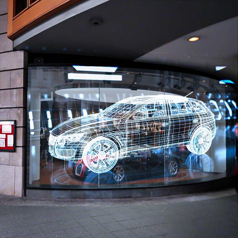
For a deep curve or cylinder, check whether the selected cabinet design can achieve the required shape and dimensions. Flexible-module cabinets are one option. For example, the C-Arc range uses soft PCB modules that flex to form concave and convex curves.
Compatibility and Structural Approval
Ask the supplier to confirm that the selected cabinet models can connect at the required angles. Ask the project engineer to confirm the support arrangement and how the assembled screen transfers its weight to that support. Record these approvals on the configuration drawing, and confirm power distribution for the complete layout separately.
Check Supporting Equipment for Each Layout
List the structural supports, control equipment, power distribution and cables needed for each planned layout.
Structure and Rigging
Specify whether the screen will be ground-supported or flown, then identify the mounting points and required brackets. Have the project engineer specify the ballast, rigging and allowable loads for the venue.
Control and Signal
Check whether the selected control system can support every planned wall size and pixel matrix. Check processor and sending-system capacity, output allocation and each screen’s content-source and control connections for the complete configuration, including all screens that operate at the same time.
Power
Have a qualified electrical professional assess the site supply and power distribution for each complete configuration using the manufacturer’s rated power and electrical requirements, including all screens operating together. Record intended operating settings, such as brightness, separately.
Cabling
List cable lengths, connector types and the number of runs for each layout, based on equipment positions and cable routing.
Recheck the complete equipment list whenever the layout changes.
Check Whether Each Layout Is Achievable
Use the configuration worksheet below, with one row per planned configuration, to record the cabinets, connections, supporting equipment and unresolved requirements.
| Planned configuration | Cabinets, arrangement and quantity | Shape and connection conditions | Supporting equipment required | Assessment status | Reference and open items |
| Fill from the event plan | Fill from the confirmed combination | Separate standard items from optional ones | Listed per layout | See the four statuses below | Document and responsible party |
The Four Assessment Statuses
- Covered by the selected cabinets. The selected cabinet types and supporting equipment meet the layout in sufficient quantities, and the relevant configuration confirmations are complete.
- Needs more cabinets or additional equipment. The selected cabinet types suit the layout, but more of those cabinets, additional accessories or supporting equipment are required.
- Needs another cabinet type or solution. The layout requires a cabinet type or solution outside the current selection.
- Pending confirmation. A venue survey, missing project details or outstanding approvals could change the assessment. Use this status first whenever such items remain unresolved.
Documents to Request from the Supplier
- An assembly drawing for each planned configuration.
- The complete equipment list behind each drawing.
- The model and version of each cabinet in the build.
- The permitted combinations, including splice direction where two cabinet sizes are used.
- A list that separates standard items from optional items for corners and curves.
- Structure, control and power confirmations for each planned configuration, especially where several screens operate at the same time.
Mark any configuration that lacks supporting documentation as pending. Ask the supplier or project engineer to confirm the missing details before the affected cabinets and equipment are specified.
Conclusion
The cabinet list decides what can be built: the sizes it contains, how many of each are available, and the connections those cabinets permit. Check each planned layout against it, starting with the wall dimensions, then the proportion and pixel matrix, the features each shape depends on, and the supporting equipment behind it. Where a layout falls outside those limits, adjust the wall size or review the cabinet selection before adapting the content. Send the planned layouts and any existing cabinet details through the Chipshow Europe contact page to review the required cabinets and supporting equipment.
Frequently Asked Questions
Can one set of rental LED cabinets build different screen sizes?
Yes, within the grid its cabinets allow. A wall’s width and height are sums of whole cabinet dimensions, so the set builds the multiples of its cabinet sizes and quantities. Rearranging the same cabinets changes the balance between width and height while the total area stays the same. Adding cabinets, or a compatible second cabinet size, can extend the options where the dimensions, the permitted connection direction and the quantities allow it.
What has to match when two cabinet sizes are used in one wall?
Four conditions. The two sets of dimensions have to combine into the planned width and height. Each cabinet has to permit connection in the direction the layout needs, since joining options differ between models. The two models have to share a joining or locking system, because different systems are built as separate walls. And the quantities have to cover the cabinets needed in each column or row for the wall to stay rectangular. The assembly drawing confirms all four for the specific models.
Do curved and angled layouts need extra hardware?
It depends on how the joints are built. A gentle arc comes from the bending range each joint allows, a right angle comes from cut edges or a dedicated corner cabinet, and a deeper curve needs a cabinet design built for that curvature. Whether the locking parts are included or supplied as options varies by model, so the accessory list has to be checked against the model selected for the layout. Ask for a list that separates standard items from optional ones for corners and curves.
How can a wall’s pixel matrix be checked against the content?
Multiply the pixel dimensions of the cabinet by the number of cabinets across and down, because the same wall size produces different matrices when the arrangement changes. Compare the result with the resolution the content is produced in and with the viewing distance at which it will be read. A wall can match the planned width and height and still be too coarse for the closest viewing position.
What should be confirmed before a configuration is locked?
Ask for an assembly drawing for each planned layout, the complete equipment list behind it, and the cabinet models and versions in the build. Separate the standard items from the optional ones for corners and curves. Obtain structural confirmation from the project engineer, and confirm control and power requirements for the full configuration, including screens that operate at the same time.